Capacitive Storage Unit for Emergency Lighting Systems
- CAPACITIVE STORAGE EMERGENCY LIGHTING SYSTEM OVERVIEW
(32…95 VDC version) - CAPACITIVE STORAGE EMERGENCY LIGHTING SYSTEM OVERVIEW
(120 VAC version)
CAPACITIVE STORAGE EMERGENCY LIGHTING SYSTEM OVERVIEW (32…95 VDC version)
 General Overview
With our partnership with TDG Transit Design Group, Lexekon has been able to co-develop an LED/Capacitor based emergency lighting system which complies with the requirements as laid out within APTA SS-E-013-99 Rev 1 “Standard for Emergency Lighting System Design for Passenger Cars” as well as the requirements as laid out by FRA 49 CFR, Part 238, Passenger Equipment Safety Standards, and FRA 49 CFR, Part 239, Passenger Train Emergency Preparedness.
General Overview
With our partnership with TDG Transit Design Group, Lexekon has been able to co-develop an LED/Capacitor based emergency lighting system which complies with the requirements as laid out within APTA SS-E-013-99 Rev 1 “Standard for Emergency Lighting System Design for Passenger Cars” as well as the requirements as laid out by FRA 49 CFR, Part 238, Passenger Equipment Safety Standards, and FRA 49 CFR, Part 239, Passenger Train Emergency Preparedness. This revolutionary system can be fully charged within 15 minutes of the railcars main power coming online and can operate the LED cylinder for upwards of four hours. As well this system offers a charge and discharge cycle of 1,000,000 charges, as well as >100,000 hours of LED life.
Energy Storage Unit
The Capacitive Storage emergency lighting unit is equipped with an array of Electrochemical Double Layer Capacitors (EDLC) connected in series-parallel and to an active charge equalizer circuit.
Charging Supervisor Block
On initial power-up the charging supervisory circuit draws power from the 76 VDC bus, delivering controlled charging power to the capacitive storage unit. When full charge is achieved the charging circuit switches to standby mode drawing minimal current from the primary power bus to maintain the capacitors fully charged.
In case of temporary power loss, if only part of the stored energy in the capacitors is used, the charging circuit switches ON restoring the full charge as soon as the primary power is restored.
LED Driver
The LED driver is a high efficiency converter designed to maximize the length of time that the system provides a useful level of illumination from a given available EDLC capacitance.
A built in switch turns ON the LED driver as soon as the 76V bus drops below a set threshold voltage. In case of a short duration loss of power or in case of a brownout the LED driver turns ON then OFF and immediately the power is restored.
Installation
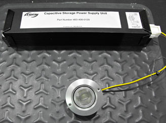
The energy storage unit (ESU) along with the charging module and LED driver, are enclosed in a prismatic box similar in size and shape to a fluorescent ballast. Quick disconnects are provided on the LED output wires and on the power side. There is no external connection to the capacitive storage unit, therefore no risk to persons or to the equipment in case of short circuit, mishandling or abuse.
The LED module is a separate piece and can be located in a convenient position while the ESU may be attached to the outside of the light fixture hosting the LED.
There are no external switches required, the operation of the emergency light is automatic. A control wire allows the unit to be configured as follows:
- Control wire tied to Positive of the input power source: emergency light comes ON with power loss or voltage dipping below threshold. Light stays ON until energy is depleted or power is restored.
- Control wire connected to a voltage source different from the main charging source. Light comes ON if the voltage on the Control line is low AND enough charge was stored in the ESU.
- Control wire not connected: Light comes ON as soon as enough charge is stored in the ESU and it stays ON continuously until charge is used up after charging power supply had been disconnected.
| Energy Storage Unit | |
| Capacitors Type | Electrochemical Double Layer |
| Number of EDLC | 6 pcs |
| Operating voltage of EDLC unit | 4.6 VDC |
| Charge/discharge cycles | 500 000 |
| Charge ballancing | Active |
| Charging Supervisor Block | |
| Operating Mode -charging phase | Constant rate of charge output |
| -stand-by | Trickle charging |
| Input Voltage | 32…95 VDC |
| Current draw @ 76 VDC | max 0.4A |
| Idle current draw @ 76 VDC | max 10mA |
| Charging time | max 10min |
| LED driver | |
| Operating Mode | Constant rate of discharge |
| Current to LED | 0.11A |
| Run time | approx 4hrs |
| Initial Light Output | min 1.5fc at 6ft |
| Light Output after 90min | min 1fc at 6ft |
| LED Start-Up | Automatic when control line drops below 20 VDC |
CAPACITIVE STORAGE EMERGENCY LIGHTING SYSTEM OVERVIEW
(120VAC version) (back to top)
General Overview
With our partnership with TDG Transit Design Group, Lexekon has been able to co-develop an LED/Capacitor based emergency lighting system which complies with the requirements as laid out within APTA SS-E-013-99 Rev 1 “Standard for Emergency Lighting System Design for Passenger Cars” as well as the requirements as laid out by FRA 49 CFR, Part 238, Passenger Equipment Safety Standards, and FRA 49 CFR, Part 239, Passenger Train Emergency Preparedness.
This revolutionary system can be fully charged within 15 minutes of the railcars main power coming online and can operate the LED cylinder for upwards of four hours. As well this system offers a charge and discharge cycle of 1,000,000 charges, as well as >100,000 hours of LED life.
Energy Storage Unit
The Capacitive Storage emergency lighting unit is equipped with an array of Electrochemical Double Layer Capacitors (EDLC) connected in series-parallel and to an active charge equalizer circuit.
Charging Supervisor Block
On initial power-up the charging supervisory circuit draws power from the 120 VDC bus, delivering controlled charging power to the capacitive storage unit. When full charge is achieved the charging circuit switches to standby mode drawing minimal current from the primary power bus to maintain the capacitors fully charged.
In case of temporary power loss, if only part of the stored energy in the capacitors is used, the charging circuit switches ON restoring the full charge as soon as the primary power is restored.
LED Driver
The LED driver is a high efficiency converter designed to maximize the length of time that the system provides a useful level of illumination from a given available EDLC capacitance.
A built in switch turns ON the LED driver as soon as the 120 VAC bus drops below a set threshold voltage. In case of a short duration loss of power or in case of a brownout the LED driver turns ON then OFF and immediately the power is restored.
Installation
The energy storage unit (ESU) along with the charging module and LED driver, are enclosed in a prismatic box similar in size and shape to a fluorescent ballast. Quick disconnects are provided on the LED output wires and on the power side. There is no external connection to the capacitive storage unit, therefore no risk to persons or to the equipment in case of short circuit, mishandling or abuse.
The LED module is a separate piece and can be located in a convenient position while the ESU may be attached to the outside of the light fixture hosting the LED.
There are no external switches required, the operation of the emergency light is automatic.
(120VAC version) (back to top)
General Overview
With our partnership with TDG Transit Design Group, Lexekon has been able to co-develop an LED/Capacitor based emergency lighting system which complies with the requirements as laid out within APTA SS-E-013-99 Rev 1 “Standard for Emergency Lighting System Design for Passenger Cars” as well as the requirements as laid out by FRA 49 CFR, Part 238, Passenger Equipment Safety Standards, and FRA 49 CFR, Part 239, Passenger Train Emergency Preparedness. This revolutionary system can be fully charged within 15 minutes of the railcars main power coming online and can operate the LED cylinder for upwards of four hours. As well this system offers a charge and discharge cycle of 1,000,000 charges, as well as >100,000 hours of LED life.
Energy Storage Unit
The Capacitive Storage emergency lighting unit is equipped with an array of Electrochemical Double Layer Capacitors (EDLC) connected in series-parallel and to an active charge equalizer circuit.
Charging Supervisor Block
On initial power-up the charging supervisory circuit draws power from the 120 VDC bus, delivering controlled charging power to the capacitive storage unit. When full charge is achieved the charging circuit switches to standby mode drawing minimal current from the primary power bus to maintain the capacitors fully charged.
In case of temporary power loss, if only part of the stored energy in the capacitors is used, the charging circuit switches ON restoring the full charge as soon as the primary power is restored.
LED Driver
The LED driver is a high efficiency converter designed to maximize the length of time that the system provides a useful level of illumination from a given available EDLC capacitance.
A built in switch turns ON the LED driver as soon as the 120 VAC bus drops below a set threshold voltage. In case of a short duration loss of power or in case of a brownout the LED driver turns ON then OFF and immediately the power is restored.
Installation
The energy storage unit (ESU) along with the charging module and LED driver, are enclosed in a prismatic box similar in size and shape to a fluorescent ballast. Quick disconnects are provided on the LED output wires and on the power side. There is no external connection to the capacitive storage unit, therefore no risk to persons or to the equipment in case of short circuit, mishandling or abuse.
The LED module is a separate piece and can be located in a convenient position while the ESU may be attached to the outside of the light fixture hosting the LED.
There are no external switches required, the operation of the emergency light is automatic.
| Energy Storage Unit | |
| Capacitors Type | Electrochemical Double Layer |
| Number of EDLC | 6 pcs |
| Operating voltage of EDLC unit | 4.6 VDC |
| Charge/discharge cycles | >1 000 000 |
| Charge balancing | Active |
| Charging Supervisor Block | |
| Operating Mode -charging phase | Constant rate of charge output |
| -stand-by | Trickle charging |
| Input Voltage | 120Vac +/_25% |
| Current draw @ 120 VAC | max 0.2A |
| Idle current draw @ 120 VAC | max 80mA |
| Charging time | max 15min |
| LED Driver | |
| Operating Mode | Constant rate of discharge |
| Current to LED | 0.11A |
| Run time | approx 3hrs |
| Initial Light Output | min 1.5fc at 6ft |
| Light Output after 90min | min 0.9fc at 6ft |
| LED Start-Up | Automatic when power line drops below 80 VAC |